
Product Brief
Description
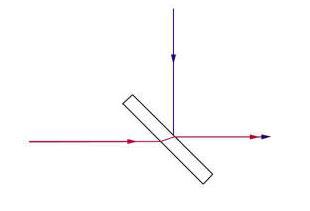
Laser beam Combiner is ideal for applications where diode lasers are being used for system alignment. Designed for using at 45 degree, they transmit the long wavelength beam and align it with the 90 degree reflected diode beam.
CO2 laser beam combiner commonly used on the laser marking machine, produced by the Chinese famous brand SPT laser.
Parameters
|
Wavelength:10.6μm |
Average transmission rate:>99%@10.6μm |
|
Average reflectivity:>85%@650nm |
Diameter tolerance:+0/-0.13mm |
|
Thickness tolerance:±0.25mm |
Face 1:T>99%@10.6um,45AOI |
|
Face 2:T>99%@10.6um R>85%@650nm,45AOI |
Surface accuracy:λ/2 per 1” Dia @632.8nm |
| Model | Material | Diameter(mm) | Thickness(mm) | Wavelength(μm) |
| BCZ-0.5-2 | ZnSe | 12.7 | 2 | 10.6μm T650R |
| BCZ-0.5-3 | ZnSe | 12.7 | 3 | 10.6μm T650R |
| BCZ-0.75-2 | ZnSe | 19.1 | 2 | 10.6μm T650R |
| BCZ-0.75-3 | ZnSe | 19.1 | 3 | 10.6μm T650R |
| BCZ-20-2 | ZnSe | 20 | 2 | 10.6μm T650R |
| BCZ-1.0-3 | ZnSe | 25.4 | 3 | 10.6μm T650R |
| BCZ-1.1-3 | ZnSe | 27.9 | 3 | 10.6μm T650R |
| BCZ-1.5-3 | ZnSe | 38.1 | 3 | 10.6μm T650R |
| BCZ-2-3 | ZnSe | 50.8 | 3 | 10.6μm T650R |
| BCZ-2-5 | ZnSe | 50.8 | 5 | 10.6μm T650R |
| BCZ-3-5 | ZnSe | 76.2 | 5 | 10.6μm T650R |
Problems & Solutions
The co2 beam combiner is ideal for calibration and indication systems using red light diodes. It is designed to transmit laser beams at 45 degrees, and to indicate and calibrate laser positions by reflecting 650 nm red beams at 90 degrees. The principle of the laser beam combiner is shown in the following figure:
Because the beam combiner has a certain thickness, when the laser beam is at an incidence of 45 degrees, it will make the beam axis drift. Controlling and reducing the beam drift is a common technical problem in the laser system when using the beam-combination mirror.
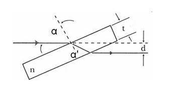
Through theoretical analysis and calculation, we discovered that the drift of the beam grows along with the thickness of the beam combiner. When the laser power is used in combination with the laser system, the system makes a reasonable choice of the accuracy requirements of the optical axis drift. Under the power configuration of 50W RF or 100W glass tube in the CO2 system, we recommend using a 2 mm thickness laser beam combiner to reduce the optical axis drift. If the power configuration exceeds this, a 3 mm thickness is recommended. If you need to calculate the optical axis drift accurately, you can contact our sales engineer. We will arrange our engineers and technicians to calculate the optical axis drift accurately according to your system configuration, and recommend a configuration of the parameters of the beam-combination mirror.
Attentions
Laser heating can absorb dirt and contaminate the surface of laser optical lens. Dust, oil vapour, water vapour, splashing of materials during cutting or marking, fingerprints and so on can contaminate the laser optical lens. Keep away from potential sources of contamination and maintain regular cleaning processes of laser lens. Under normal conditions, every worker should check the optical system before changing shifts to predict possible contamination or damage.
1. Always wear rubber/latex finger cots or gloves when operating beam combiner. Dirt and oil stains on the skin can seriously contaminate the laser lens and greatly degrade its performance.
2. Do not use any tools to operate laser beam combiner, including tweezers.
3. Out of protecting the lens, the lens should be placed on the wiping paper or cotton.
4. Do not place laser optical lens on hard or rough surfaces. The surface of optical lens can easily be scratched.
5. Do not clean or touch the exposed gold or copper surface.
6. Keep in mind that all the laser lens components are fragile.
1. Take off the laser lens with a finger cot.
2. Blow the debris scattered on the surface of the laser beam combiner with an air bag and place it on a clean and soft cotton cloth.
3. Use clean degreased cotton balls and soak them in acetone before wiping the lens surface.
4. Wash the lens with acetone, then hold the corner of the wiping paper and place the paper on the lens. Drag the paper slowly to remove the residual acetone, then dry the surface of the lens.
5. Heavily polluted metal based lens can be cleaned with a minimum polishing agents to ensure the removal of diet at first. Then use the above series methods for cleaning.
6. Finally, carefully inspect the surface of the laser optical lens under intense light. Repeat the steps if there are residual contaminants.
Guarantee
Despite choosing the best optical materials and technology, we can not completely guarantee that all laser optical lens products will not appear any defects. We provide a 30-day quality litigation period for quality problems caused by defects in optical materials and manufacturing.
1. The polluted laser lens surface which lead to the breakdown of material and coating film.
2. The damage of coating film which cased by improperly storage, laser lens should be kept avoid humidity.
3. The damage of coating film which cased by improperly cleaning methods.
4. The damage of laser lens caused by external force.

Tel: 0086-769-26380380
Business: [email protected]
Service: [email protected]
Address: #3201, Dongjiang Star Commercial Center, Dongguan , Guangdong,China