


Introduction: The laser cutting machine itself uses a flying optical path system. During long-term work, the optical path will slightly deviate, which will have a great impact on the cutting effect. Therefore, regular inspection of the light path and adjustment is a very necessary task. Before adjusting the optical path of the laser cutting machine, we must have enough knowledge of the laser tube, the mirror frame and the focus lens. Let’s introduce it to you.
How to adjust the light path of laser cutting machine? Many new customers are still unfamiliar with the operation of adjusting the optical path after purchasing the laser cutting machine, but the laser cutting machine manufacturers will provide training services for customers. However, many customers will forget the operation method very quickly, so here, SPT laser has compiled a tutorial on the laser path adjustment of the laser cutting machine to share with you.
What circumstances does the laser cutting machine need to adjust the optical path?
The laser cutting machine itself uses a flying optical path system. During long-term work, the optical path will slightly deviate, which will have a great impact on the cutting effect. Therefore, regular inspection of the light path and adjustment is a very necessary task. Before adjusting the optical path of the laser cutting machine, we must have enough knowledge of the laser tube, the mirror frame and the focus lens. Let’s introduce it to you.
1. Mirror frame A
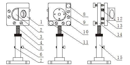
Part of the reflector in the laser optical path of the laser cutting machine
1. Light target placement rack
2. Mirror
3. Spring lock screw
4. Adjusting screw
5. adjusting screw nut
6. Locking screw a
7. Locking screw b
8. Adjusting screw M1
9. Mirror locking plate
10. Adjusting screw M
11. Adjusting screw M2
12. Spring
13. Mirror mounting plate
14. Mounting plate
15. Base
2. Mirror frame B (All is the same except that the mounting base plate is different from the A frame)
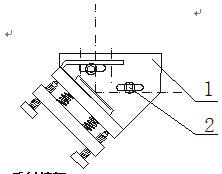
Laser mirror frame structure
2. Lock screw
3. Mirror frame C
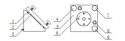
Mirror frame structure
1. Mirror adjustment plate
2. Mirror
3. Locking screw
4. Adjusting screw M1
5. Mirror adjustment plate
6. Mirror compression plate
7. Adjusting screw M
8. Locking screw
9. Adjusting screw M2
4. Laser lens
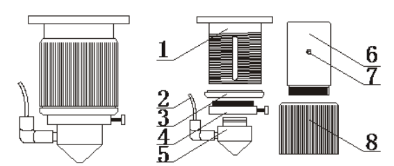
Laser lens structure diagram
1. Focusing inner tube
2. Air inlet tube
3. Limiting coil
4. Gas nozzle transition sleeve
5. Gas nozzle
6. Len tube
7. Limiting screw
8. Adjusting sleeve
Understand the names of the various components, let's teach you how to adjust the light path of laser cutting machine
Four light path adjustments:
1. The adjustment of the first light, attach the textured paper to the light target hole of the mirror A, and the light is manually jogged (note that the power is not too high at this time), fine turn the base of the mirror A and the laser tube bracket so that The laser light hits the center of the target hole, and the light cannot be blocked.
Measuring method of focal length:
Make the use of the focal length scale from the laser cutting machine manufacturer, place the nozzle up and down on the number 5 of the focal length scale. At this time, the light is the brightest and strongest, and then lock the screw.
As shown in the cubic picture
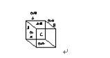
The position of the light path of the laer tube
1.The cutting surface is biased to the left, which means the laser head is too low or the mirror is too high. eg, inclined to the D side, indicating that the light is low
There are two solutions to the biased light path:
Lower the mirror C, and at the same time turn M1, M2, M3 counterclockwise;
Raise the laser tube (clockwise)
There are two solutions if the light path is biased to right:
Raise the mirror C, and at the same time turn M1, M2, and M3 clockwise;
Lower the laser tube (counterclockwise)
Turn t the mirror mount B clockwise,
Turn M1, M2, and M3 on mirror B (clockwise)


