


TR Series CO2 Laser Tube
During the laser processing, it has the functions of red light preview and red light positioning to help users better plan the utilization rate of processed materials. At the same time, the visible red light greatly reduces the obstacles caused by the invisibility of the CO2 laser to the laser optical path debugging. It helps users to accurately visually observe the transmission path of the laser, making the adjustment of the optical path more precise and convenient, and reducing the risk of being burned by the CO2 laser. Especially for people who are not experienced in debugging the optical path of the laser machine, the operation safety is greatly improved.
The use of red light to adjust the light path is divided into 3 parts, longitudinal light path adjustment, horizontal light path adjustment and vertical light path adjustment.

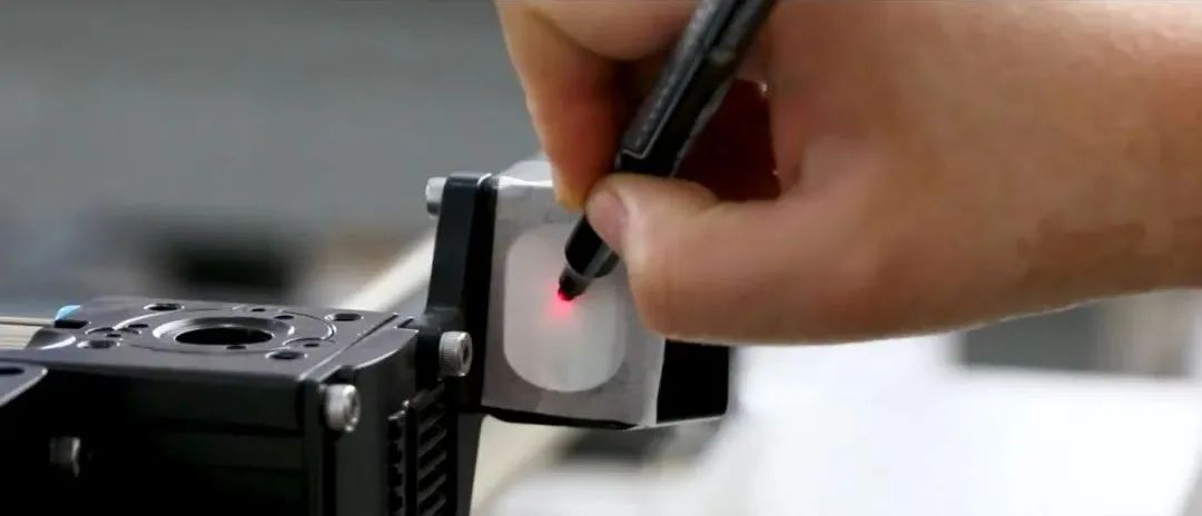
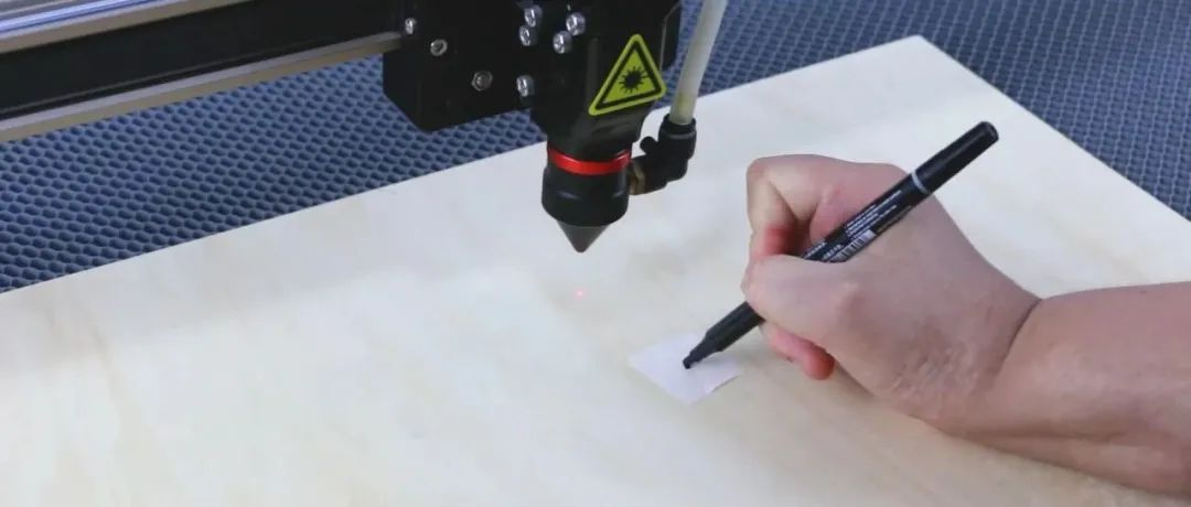
Move the X-axis part of the machine to the position closest to the light source, attach the textured paper to the second reflector frame, and use a pen to make a mark on the textured paper at the same spot as the red light.
Then let the X-axis part of the machine go to the position farthest from the light source.
Adjust the red light that has deviated from the mark point through the adjusting screw on the first reflector frame so that it coincides with the mark point again.
The action above needs to be repeated 2-3 times until the red light does not deviate from the mark point, and the adjustment of the longitudinal light path is completed.

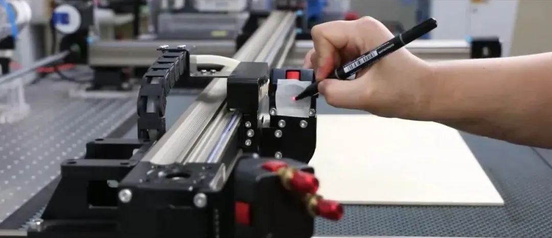
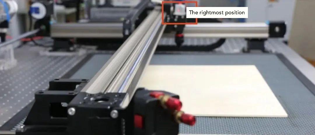
Move the laser head to the leftmost position, paste the textured paper, and use a pen to make a mark on the textured paper at the same spot as the red light.
Move the laser head to the rightmost position.
Adjust the red light that has deviated from the mark point through the adjusting screw on the first reflector frame so that it coincides with the mark point again.

The above actions need to be repeated 2-3 times until the red light does not deviate from the mark point, and the adjustment of the horizontal light path is completed.

Place the wooden board on the platform of the machine and make a dot mark with textured paper.
Move the laser nozzle down to the surface of the textured paper, and move the wooden board so that the mark coincides with the center of the laser nozzle.
Then move the laser nozzle up.
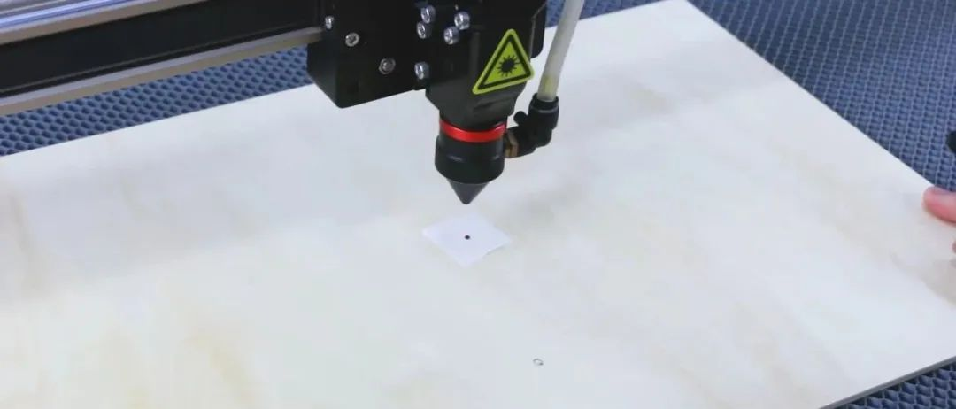
Adjust the adjusting screw on the third reflector frame so that the red light coincides with the mark point. The adjustment of the vertical light path is completed.
At this point, all light path adjustments are completed.

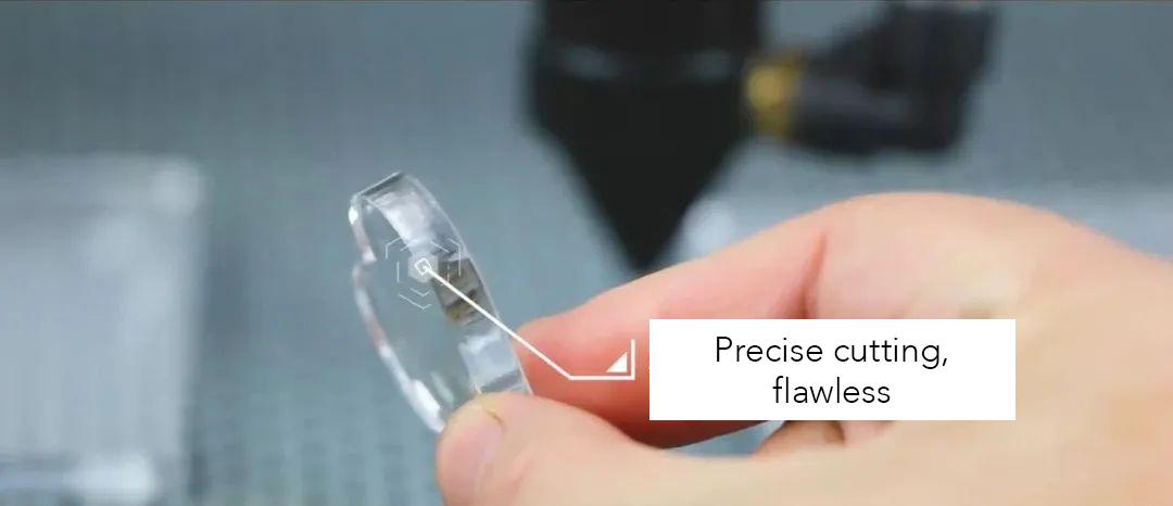
Material: acrylic 5mm thick


